Understanding Pipeline Analog to Digital Converter. Sample Jitter Calculation Assuming Broadband Phase Noise.

How To Simulate Multiple Sensors Using Arduino Uno In Proteus Sensor Arduino Multiple
UART or universal asynchronous receiver-transmitter is one of the most used device-to-device communication protocols.

. Understand the architecture and operation of Pipeline Analog to Digital Converter. AMPM and 24 Hour Clock Adding and. The unit is similar to the units dBov and decibels relative to overload dBO.
If the sensor is too large for the lens design the resulting image may appear. Timely updates on new products reference designs design tools technical articles and design resources. Note that the Rth of 2k35 is in series with the 1k so low pass has R 3k35 with 0u1 F.
For example a signal that reaches. Is the burden for the CT. Crystal oscillators generally offer the lowest possible phase noise and jitter and some examples are shown for comparison in Figure 6.
5G and capacity build-out strategies it is critical to have a full understanding of beamforming antenna capabilities including the variations and appropriate use cases for each type. You can change the time by moving the hour and minute hands of the analog clock. The example presented shows that the sample of the autocorrelated signal will be at its maximum value when the overlapping signal best matches the given signal.
She holds a B. R19 10E 10R 10 ohm 14 watt. In this case it happens when time-shift is zero.
Find key performance characteristics of pipeline ADCs and get more information today. Try setting the time to these different values. Thus here we find that the samples of the autocorrelated signal Rxx are -1 0 6 0 -1 where 6 is the zeroth sample.
IMPORTANT NOTICE Texas Instruments Incorporated and its subsidiaries TI reserve the right to make corrections modifications enhancements improvements and other changes to its products and services at. In Electrical Engineering and has an industry background in analog design and EDA. The CCD sensor is itself an analog device but the output is immediately converted to a digital signal by means of an analog-to-digital converter ADC in digital cameras either on or off chip.
This chapter gives an overview of the subject of CMOS analog circuit design defines notation and convention makes a brief survey of analog signal processing and gives an example of analog CMOS design with emphasis on the hierarchical aspect of the design. For the past 18 years she has worked in technical marketing and product management focusing on parasitic extraction. A special subset of the video driver is the video-distribution amplifier see Table 5Built to drive multiple loads they offer higher isolation.
The level of 0 dBFS is assigned to the maximum possible digital level. Without this understanding planners risk over- or under-engineering parts of their networks resulting in unnecessary costs insufficient performance or both. Typical 1 2 Sensor MP 031.
Instead of using binary-weighted current sources we can use current sources of the same value to implement a DAC. In this case an appropriate number of switches should be turned on to produce a given analog voltage level. Shown as terminals 1 and 6.
C1 0u1 farad. Decibels relative to full scale dBFS or dB FS is a unit of measurement for amplitude levels in digital systems such as pulse-code modulation PCM which have a defined maximum peak level. Choosing A Video IC Tables 3 and 4 show large-signal bandwidth 2V P-P slew rate differential gain and phase and supply voltage for Maxims most popular video drivers buffers and receivers with single-ended and differential outputs.
This method which uses a unary-weighted current sourcebased structure is shown in Figure 6. This article shows how to use UART as a hardware communication protocol by following the standard procedureWhen properly configured UART can work with many different types of serial protocols that involve transmitting and receiv. 21 Analog-to-Digital Converter ADC An ideal ADC uniquely represents all analog inputs within a certain range by a limited number of digital output codes.
A 150dBc 10 log10 200 106 001 6 150dBc 83dB 67dBc 1ps Figure 5. All the oscillators shown have a typical 1f corner. Claudia Relyea is a Principal Product Engineer in the Design to Silicon Division of Mentor a Siemens Business.
Chapters 2 and 3 form the basis for analog CMOS design by covering the subjects of CMOS. The ADS1291 ADS1292 and ADS1292R are multichannel simultaneous sampling 24-bit delta-sigma ΔΣ analog-to-digital converters ADCs with a built-in programmable gain amplifier PGA internal reference and an onboard oscillator. In Terms 5 and 6 students design and build an industry-style project using tools and techniques that they have learned in Terms 1-4.
Students plan out their projects what tools they will use to build them put together a project plan and build and. Forms a low pass filter to the analog input port RA0. The diagram in Figure 1 shows that each digital code represents a fraction of the total analog input range.

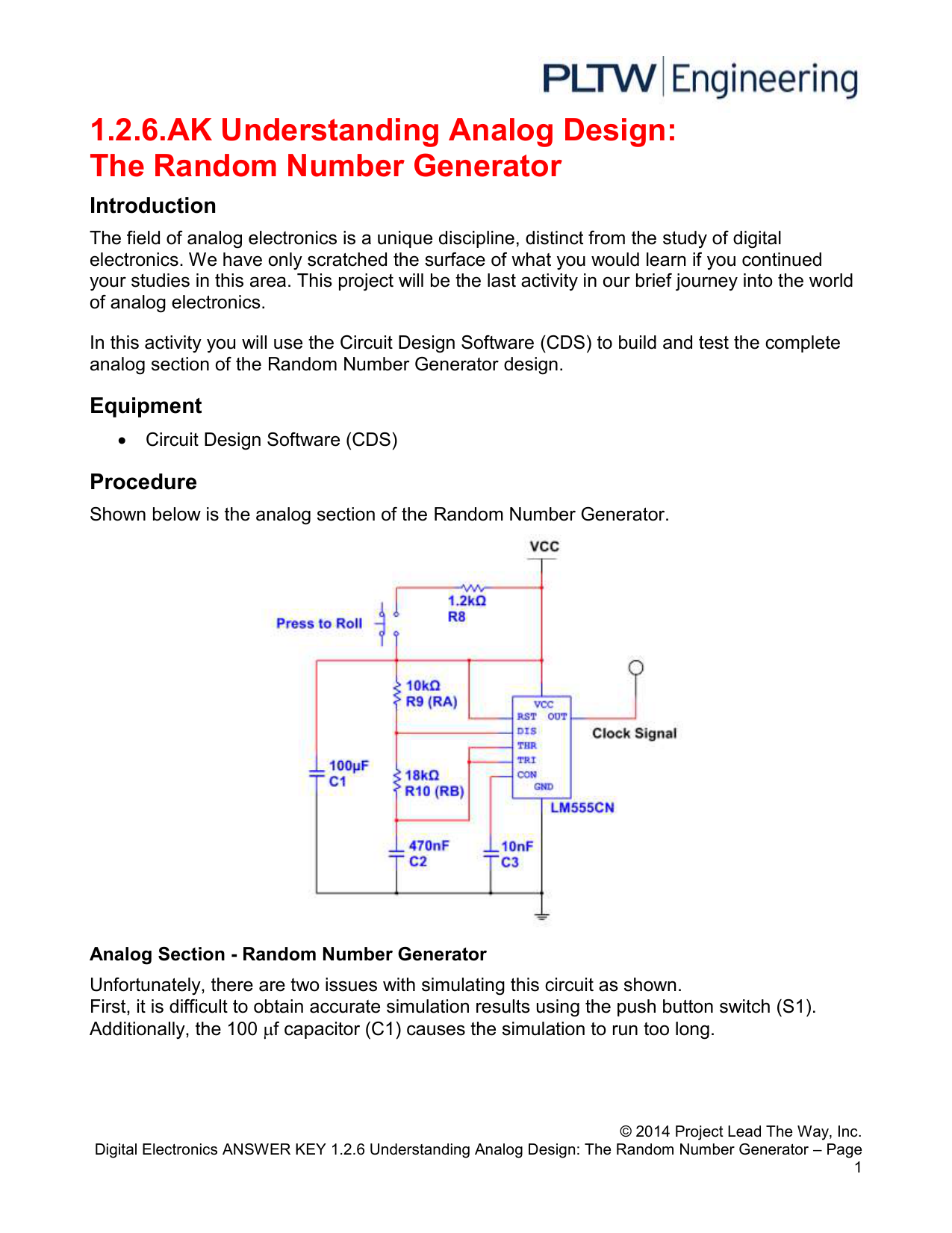
1 2 6 Ak Understandinganalogdesign Rng

Versatile Power Supply Detailed Circuit Diagram Available Power Supply Circuit Electronic Schematics Circuit Diagram

1 2 6 Ak Understandinganalogdesign Rng

Light Blue Triangular Abstract Design Watch Watch Design Abstract Design Triangular

Pin By Andreas Cahyo Febrianto On Electronics Circuit Electronics Circuit Electronics

Find More Infos And Buy Watch For Low Prices Brand Tetonis Original Produk Sesuai Gambar Pilih Gambar Yang Akan Jam Tangan Jam Tangan Tali Jam Tangan Wanita

Image Result For Ne556 Pinout Stopwatch Timer Timer Alarm Timer

0 comments
Post a Comment